Honda Xr200 Wiring Diagram, Skygo150 Voltage Regulator for XR200/Actual Wiring/Honda XR200 Modified/Supermoto/DIY Garage PH, 10.03 MB, 07:18, 10,383, D I Y Garage PH, 2021-01-23T08:48:03.000000Z, 19, Iam looking for a 1982 honda xr200 wiring diagram, www.justanswer.com, 904 x 703, jpeg, wiring diagram 1982 honda xr200 xt200 yamaha manual iam motorcycle looking 1981 mechanic bikee wire, 20, honda-xr200-wiring-diagram, Anime Arts
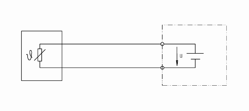
My question is regarding the ads1120 part and two rtd wiring in two wires mode. Is it possible to use it as described in a basic guide to rtd measurement §2. 7 (the following picture). Rtd / ohms / thermocouple / mv input module, 8 individually configurable isolated points, 36 pin. Lhcb the lhcb rich detector control system requirements for.
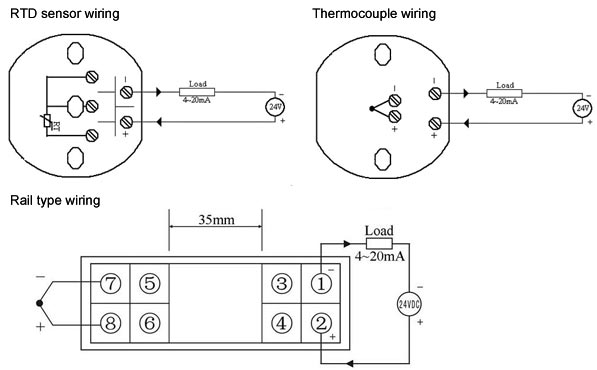
The resistance re is taken from the resistance element and is the value that will supply us with an accurate temperature measurement. The most common pt100 rtd used in industry is one that changes resistance at the rate of about 0. 385 ohms for every degree celsius rise in temperature. We know the resistance of a pt100 sensor at zero degrees celsius is 100 ohms, so the resistance we would expect at 100 degrees celsius would be 138. 5 ohms. The 385 factor comes from the equation. Inquiry about 110v, 120v/60hz pa200b~pa1000b single or double speed small portable lifting mini electric wire rope cable motor. Pa1000 wiring diagrams as i have pulled remote off the unit thanks. When wiring with two wires, first jumper across a1 and b1and a2 and b2 respectively, then connect pt100 sensors and to the rtd module according to the following diagram on the left. Craftsman mower diagram deck lt2000 parts lawn belt 247 mtd riding tractor 42 drive lt2500 diagrams yard machine sears murray. T:\. \sunearth\resistor_table_pt1000. doc seite 1 von 2 speicherdatum:
4-wire (Pt100) and 2-wire (Pt1000) ELMB temperature adapter schematic. | Download Scientific Diagram

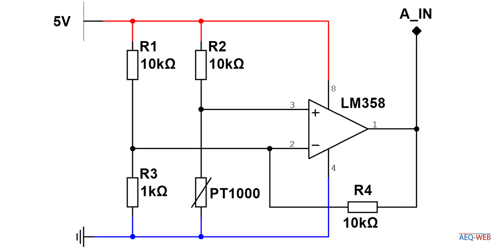
Pt1000 Temperature Sensor Circuit Diagram - Wiring View and Schematics Diagram
Pt1000 Temperature Sensor Circuit Diagram - Wiring View and Schematics Diagram

microcontroller - PT1000 2 wire probe. Can I add third wire? - Electrical Engineering Stack Exchange

Best Pt100 To 4 20ma Pt1000 To 0 5v Converter Pt100 Transmitter Pt100 Temperature Or Thermal
[Resolved] ADS1248 SCHEMATIC FOR 2-WIRE PT1000 RTD - Precision Data Converters Forum - Precision
Rtd Pt100 Circuit Diagram - Wiring View and Schematics Diagram

Pt100 in 2-, 3- or 4-wire connection? - WIKA blog

Pt1000 Temperature Sensor Circuit Diagram - Wiring View and Schematics Diagram
pt1000 rtd table | www.microfinanceindia.org


